Introduction
The effect of time dilation relates to the Einstein’s special relativity [1]. According to the latter, the relativistic time dilation is a difference in the course of time recorded by two observers, which are respectively in the moving inertial reference system (IRS) and in the IRS, which is stationary with respect to the first, while in the moving IRS the clock turns out to be slower than the course of time in a stationary IRS This phenomenon was confirmed, for example, by the Hafele-Keating experiment. [2] The relativistic time dilation has a certain effect on the signals and on the linear system characteristics [3], [4]. The present article discusses the possible ways to compensate for this effect in the frequency and time domain. Subsequently, all the notations with acute accent (´) will be related to the moving IRS.
Formulation in the time domain
The linear system can be represented by an ordinary differential equation with constant coefficients [5]:
anx(n)(t) + an-1x(n-1)(t) + … + aоx(t) = f(t) (1)
Placed in a moving IRS the system is affected by relativistic time delay, and the coefficients in (1) are expressed in the form [3]:
ak´ = γkak , k = 0 … n (2)
where γ - Lorentz factor, γ = 1 /![]() (v – relative velocity of IRS, c – light speed in free space and γ > 1) [1].
(v – relative velocity of IRS, c – light speed in free space and γ > 1) [1].
Consider the impulse characteristics of a linear system in a stationary and moving IRS as G(t) and G´(t) respectively. In turn these characteristics depend implicitly on the parameters of the linear system. If we represent both characteristics by the corresponding set of samples, taking into account the Nyquist frequency and the attenuation [6], then the ordinary least-squares technique can be used for adjustment of the system parameters [7]. We define the objective function as a proximity measure of two sample sets:
Φ(p1,p2, …,pm) =![]() (gk – gk´)2 (3)
(gk – gk´)2 (3)
where
gk´ - samples of the impulse response G´(t), depending on the variable parameters (p1,p2, …,pm)
gk - samples of the impulse response G(t)
The choice of parameters and their quantity in (3) depends on system features. Within this statement of the problem, the minimization of the function (3) is next step to be performed. Herewith, existing numerical methods of multidimensional optimization can be used which are varying in specific strategies for selecting of the increment vector for variable parameters (Δp1,Δp2, …,Δpm) [7].
The block diagram for the adjustment in time domain by using ordinary least-squares is shown in Fig. 1.

Fig. 1 – Block diagram of the adjustment in the time domain
On this diagram, the input of the linear system (LS) is fed by delta function δ´(t). The impulse response G´(t) is transferred to the sampler (S), at the output of which appears a set of samples gk´. The specific of this procedure is that the samples gk and gk´ are produced with a time step which is the subject to the Nyquist-Shannon theorem [6] and the Lorentz transformation [1].
Note that in the case of a pulse (discrete) linear system the sampler is the standard part of it [5]. However, for temporal matching, additional oversampling with subsequent digital filtering may be required to remove high-frequency components that do not satisfy the conditions of the Nyquist-Shannon theorem [6].
Next, the appliance realizing the ordinary least-squares (OLS) is used, which includes a multidimensional optimization algorithm generates a vector of parameter increments transmitting to the linear system. It is assumed that the system has a gear for adjustment of parameters by using these increments.
The parameter adjustment process must be stopped at the moment when the specified value (σ) of the objective function is reached, that is:
Φ(p1,p2, …,pm) < σ (4)
As another termination condition, the value of the time interval may be set, by which no further increment vector was found, leading to the further decrease of the objective function.
Formulation in the frequency domain
The frequency response of a linear system can be obtained on the basis of the differential equation (1). Next, assuming in (1) zero initial conditions f(t) = δ´(t) follows the operator representation with transfer function [5]:
R(s) = (ansn + an-1sn-1 + … + aо)-1 (5)
With the substitution s = jω the system frequency response is determined. On the other hand, the frequency response can be obtained from the impulse response by means of the Fourier transform [6].
Consider the amplitude-frequency characteristics of the linear system in a stationary and moving IRS as R(ω) and R´(ω) respectively. In turn these characteristics depend implicitly on the parameters of the linear system. Then, by analogy with the formulation of the problem in the time domain, the objective function may be defined as a proximity measure in the form:
Φ(p1,p2, …,pm) =![]() (rk – rk´)2 (6)
(rk – rk´)2 (6)
where
rk´ – samples of the impulse response R´(t), depending on the variable parameters (p1,p2, …,pm)
rk – samples of the frequency response R(ω)
The sum on the right-hand side of (6) can be supplemented by the same components but containing the samples of the phase characteristics or one can confine with only these components. However, the final choice of the function (6) must be made by taking into account the features of the system and the actuality of specific characteristic.
The block diagram for adjustment in the frequency domain by using ordinary least-squares is shown in Fig. 2.

Fig. 2 – Block diagram of the adjustment in the frequency domain
This block diagram differs from the Fig. 1 only in the way that the discrete Fourier transform appliance (DFT) is additionally used [6] in order to obtain the samples of the amplitude-frequency characteristic obtained from the of generated impulse response. By analogy with the formulation of the problem in the time domain, the parameter adjustment process must be stopped when inequality (4) is fulfilled or when the run time is exceeded, during which no single incremental vector has been found, that would lead to a further decrease of the objective function.
Computer simulation
For the experimental verification of the compensation methods described above, computer simulation of a second-order linear system, represented by a series LCR circuit, is carried out. Moreover, the following parameters are used: γ equal 2.5, L equal 25mH, C equal 0.5nF and R equal 50kΩ.
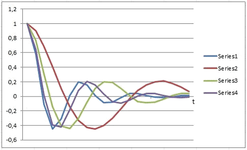
When simulating in the time domain (in accordance with the block diagram in the Fig. 1) L´ was taken as variable parameter. The simulation results by two OLS iterations are shown in the Fig. 3, where, for clarity, the points of impulse characteristics are connected by lines.

Series1 - G(t) by L=25mH, Series2 - G´(t) by L´=62.5mH, Series3 - G´(t) after the 1st iteration by L´=37.5mH, Series4 - G´(t) after the 2nd iteration by L´=28.75mH
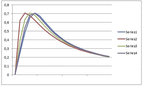
When simulating in the frequency domain (in accordance with the block diagram in the Fig. 2) C´ was taken as variable parameter. The simulation results by two OLS iterations are shown in the Fig. 4, where, for clarity, the points of amplitude-frequency characteristics are connected by lines.

Series1 – R(t) by C=0.5nF, Series2 –R´(t) by C´=1.25nF, Series3 – R´(t) after the 1st iteration by C´=0.75nF, Series4 – R´(t) after the 2nd iteration by C´=0.59nF
From these results it may be concluded with confidence that further iterations lead to complete compensation of the relativistic time dilation impact on the linear system under consideration. Thus, the principal possibility of the compensating on the bases of the represented block diagrams is confirmed.
Direct compensating
In some cases it is possible to obtain analytical relationships that establish a specific connection between parameters of the linear system and Lorentz factor [4]. As such an example, consider series LC circuit without losses. As well-known, the period of damped oscillations in this circuit is determined by the Thomson formula [8]:
T = 2π ![]() (7)
(7)
Hence the oscillation frequency will be equal:
ω = 1 /![]() (8)
(8)
Then for this system in a moving IRS:
ω ´ = 1 /![]() (9)
(9)
In this case, as was shown in [4]:
L´ = γ·L (10)
C´ = γ·C
Thus, in order to provide the equality ω´ = ω (for compensation in the frequency domain) it is sufficient to change the values of L’ and C ‘, that is
L´ => L´ / γ (11)
C´ => C` / γ
Note that this adjustment of the parameters leads to complete compensation of the time dilation impact on the frequency response. Another example of the direct compensating is described in [9], where parameter adjustment was completed for the on-board equipment of the global navigation system.
Conclusions
The methods for compensating the relativistic time dilation impact on the characteristics of linear systems are proposed. In connection with this, two formulations of the problem for the parameter adjustment of linear systems – in the time domain and frequency domain – is considered. In both cases, the compensation for the time dilation effect is formulated as OLS and minimizing of the objective function as proximity measure of the two characteristics. The computational complexity of this minimization procedure (generally, multidimensional) mostly depends on the number of variable parameters and may require rather powerful computing appliances. Hereby, it seems appropriate to use specialized processors of the kind FFT [10]. On the other hand, by known analytical relationships, reflecting the relativistic time dilation impact on the characteristics of a linear system, direct adjustment of the parameters is possible, up to the complete compensation.
References
- Forshaw Jeffrey, Smith Gavin. Dynamics and relativity. John Wiley & Sons: 2014. 344 p.
- Hafele J. C., Keating R. E. (July 14, 1972). “Around-the-World Atomic Clocks: Predicted Relativistic Time Gains” (PDF). Science. 177 (4044): 166–168.
- Soutchilin V. A. Relativistic Time Dilation Impact on Dynamics and Stability of Linear Systems // Современные научные исследования и инновации. 2018. №2 [Электронный ресурс]. URL: http://web.snauka.ru/issues/2018/02/85729
- Soutchilin V. A. Relativistic Approach to Signals and Systems // Современные научные исследования и инновации. 2017. №11 [Электронный ресурс. URL: http://web.snauka.ru/issues/2017/11/84761
- Попов В. Л. Теория линейных систем регулирования и управления. М.: Наука, 1989. 304 с.
- Oppenheim A. Digital Signal Processing. Prentice-Hall: 1978. 267 p.
- Черноруцкий И. Методы оптимизации. Компьютерные технологии. БХВ-Петербург, 2011. 384 с.
- Атабеков Г. И. Теоретические основы электротехники. Линейные электрические цепи. М.: Лань, 2008: 591 с.
- Ashby Neil. Relativity in the Global Positioning System. Living Reviews in Relativity. Department of Physics, University of Colorado, Boulder, Colorado 80309-0390 USA.
- You Jaehee. Algorithm and architecture for implementing FFT array processor with wafer scale integration. Cornell University: 1990. 322 p.
