РАЗРАБОТКА НОВОГО МАГНИТНО-ГИДРАВЛИЧЕСКОГО ДВИГАТЕЛЯ ПОВЫШЕННОЙ ЭНЕРГОЭФФЕКТИВНОСТИ
Казанский национальный исследовательский технический университет им. А.Н. Туполева – КАИ
кандидат технических наук, доцент кафедры «Теплотехники и энергетического машиностроения»
Аннотация
Статья посвящена разработке нового магнитно-гидравлического двигателя повышенной энергоэффективности и экономичности. Рассмотрена проблема загрязнения окружающей среды и проблема применения существующих энергоустановок. Представлены материалы описания заявки на изобретение.
Ключевые слова: двигатель, жидкость, капсула, магнит, поплавок, эффективность
ELABORATION OF A NEW MAGNETIC-HYDRAULIC ENGINE WITH INCREASED ENERGY EFFICIENCY
Kazan National Research Technical University named after A.N. Tupolev – KAI
PhD, Associate Professor of Heat and Power Engineering Department, Kazan, Russia
Abstract
The paper is devoted to elaboration of a new magnetic-hydraulic engine of high level of energy, economy and ecology efficiency. A problem of environment pollution and a problem of existing power plants application are highlighted here. In addition, true parts of an invention are presented for better understanding.
Рубрика: 05.00.00 ТЕХНИЧЕСКИЕ НАУКИ
Библиографическая ссылка на статью:
Алтунин К.В. Разработка нового магнитно-гидравлического двигателя повышенной энергоэффективности // Современные научные исследования и инновации. 2021. № 8 [Электронный ресурс]. URL: https://web.snauka.ru/issues/2021/08/96475 (дата обращения: 01.08.2026).
INTRODUCTION
Nowadays it is not a secret that there are some unsolved problems on the Earth including, first of all, ecology and energy ones. The ecological situation gets worse all over the world every single year. For example, the number of cities in which the permissible pollution indicators established by the World Health Organization are increased really exceeds 50%. About 36 million Russians live in cities where air pollution is higher than worldwide sanitary standards indicate by 10 %.
It is true that about 48 kg of various carcinogenic substances are inhaled by a megalopolis resident per year. Over the past 40 years, the amount of fresh water per person in the world has decreased by 60%, and over the next 25 years, a further 2-fold decrease is just expected. By 2030, the world’s population will increase up to 8.5 billion people [1].
Leading specialized organizations, based upon the quantitative and qualitative analysis of development indicators of the energy system, present interesting development forecasts and scenarios of the world energy sector. According to some calculations, in the period up to 2050, the global demand for energy is expected to grow by about 50%, and for electricity – by almost 100%. At this rate of growth and with the use of organic fuels, it is obvious that environmental pollution will continue further.
Nowadays it is known that modern renewable energy provides about 8% of the total energy consumption for heating and cooling due to biomass energy and only to a small extent from solar thermal and geothermal energy. Approximately 3/4 of the world’s heat consumption is provided by organic fuel. Although the total capacity and heat generation from renewable energy sources continue to grow, in 2015, due to the fall in oil prices, the growth rate decreased. One of the goals of the sustainable development of the world is to ensure universal access to affordable, reliable and modern energy services based upon renewable energy sources. Global energy consumption is suggested to double by 2030. At the same time, due to the import of oil, gas and coal, the EU will meet its energy needs by 70%, the USA by 40%, Japan by 90% [2].
Thus, it will not be possible to completely avoid climate change, but if new energy-efficient solutions and eco-friendly engines are introduced, it will be possible to slow down this process. The article discusses the idea of creating an environmentally friendly magnetic-hydraulic engine.
The goal of this work is to develop a new energy-efficient, safe and completely environmentally friendly magnetic-hydraulic engine with possibility of producing work and generating the cheapest electricity.
ELABORATION OF A NEW MAGNETIC-HYDRAULIC ENGINE
The current description of a proposed magnetic-hydraulic engine is based on one invention of the author [3], which can be reviewed with the following figures 1-10 where: 1 is a liquid volume, 2 is a (liquid) capsule, 3 is a flout, 4 is a support, 5 are scales, 6 is a magnet, 7 is a magnet, 8 is a (liquid) capsule, 9 is a liquid volume, 10 is a magnet, 11 is a float, 12 is a thread or a cord, 13 is a wheel, 14 is a bracing, 15 is a wheel, 16 is a magnet, 17 is a bracing, 18 is a wheel, 19 is a reverse mechanical transmission, 20 is a wheel, 21 is a support, 22 is a support, 23 is an output pulley, 24 is an input pulley, 25 is a support, 26 is a support, 27 is a magnetic line, 28 are wheels, 29 is a support, 30 are wheels, 31 is a support, 32 is a (liquid) capsule, 33 is a magnet, 34 is a float, 35 is a liquid volume, 36 is an attachment, 37 is a guiding part, 38 is a plank, 39 is a rail, 40 is a pulley, 41 is a shaft, 42 is cord, 43 is a rail, 44 is a counterweight, 45 is a cord, 46 is a plank, 47 is a guiding part.
It is known from the physics course that when a volume of any body is immersed in liquid (for example, fresh water), the so-called Archimedes’ force appears [4]. Archimedes’ law is one of the laws of statics of liquids (hydrostatics) and gases (aerostatics): a body immersed in liquid or gas is affected by a buoyancy or lifting force Fa, equal to the weight of the volume of liquid or gas V, squeezed by a part of the body immersed in liquid or gas with a density ρ:
![]() (1)
(1)
where g is the gravitation acceleration, m/s2.
Let’s observe Figure 1 where is liquid volume 1 stays in capsule 2 on the level H1 from the bottom of the capsule. There is float 3 on the surface of liquid (e.g., fresh water) that is rigidly connected to support 4.
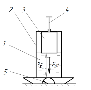
Fig. 1 The system of a float and a capsule with liquid inside
We can assume that a weight of float 3 together with support 4 and also a weight of capsule 2 (without liquid) are negligibly small in comparison with a weight of liquid volume 1, that’s why it is just possible to neglect them here. Let air be inside a leakproof shell of float 3. So, the gravity force of liquid volume 1 is equal to Fg1. Now let’s start pressing down on support 4, by approaching the submersion of float 3 into liquid; then stop motion, when float 3 is fully submerged in liquid, and a liquid level is H2 (Fig. 2), then the Archimedes’ force appears Fa2 that balances the force F2, i.e., Fa2=F2, while scales 5 show another, namely a greater weight: Fgs=Fg1+Fа2 or Fgs=Fg1+F2.
Now we can fix support 4 with the body of liquid capsule 2, for example, this can be done with a rope, a chain, etc. (not given in the description), i.e., we can destroy the force F2, which balances the force Fа2. Then scales 5 will again show the weight Fg1 and Fgs=Fg1.
Thus, on the basis of Newton’s third law and Archimedes’ law, it can be stated: “The gravitational force of a liquid volume in a capsule increases by as much as the Archimedes’ force of a submerged body increases in this liquid, provided there are no direct force contacts between the capsule body containing liquid and the shell of the submerged body” [5].
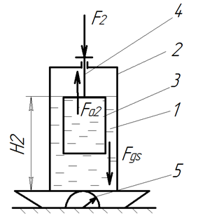
Fig. 2 A float is submerged into liquid of one capsule
Let’s consider Fig. 3 and 4, where magnet 6 is rigidly installed inside float 3 (for example, it can be installed on the bottom of float 3, on the wall, etc.). Magnet 6 can be a permanent magnet or an electric one (further here is a description involving only permanent magnets). If we again neglect the weight of float 3 together with support 4, it turns out that only magnet 6 creates the weight Fg3, so scales 5 will show a greater total weight of the entire system, and the level H1 of liquid volume 1 will rise.
With a similar full submersion of float 3 into liquid volume 1 using pressure on support 4, scales 5 will show a greater weight, but the liquid level will rise again to the same level H2, since the volume of float 3 has not changed (Fig 4). Then in this case the Archimedes’ force appears that balances the force F2, i.e., Fa2=F2, and scales 5 will show other greater weight such as: Fgs=Fg1+Fg3+Fа2 or Fgs=Fg1+Fg3+F2.
Now imagine that in addition to magnet 6, there is also magnet 7 located outside (Fig. 5). In this case, float 3 can sink under the liquid level (for example, fresh water) in the following case: when magnets 6 and 7 are attracted to each other (for example, they can be put by different poles). Thus, force F4 will pull float 3 downwards opposite to force Fa2. Then we can obtain the following balance: Fgs=Fg1+Fg3+Fа2 or Fgs=Fg1+Fg3+F4.
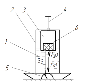
Fig. 3 A magnet creates an additional weight to a capsule
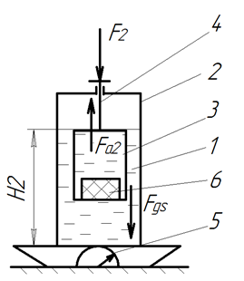
Fig. 4 A float with a magnet inside being submerged into liquid of a capsule
It is not difficult to guess that the distance between magnets 6 and 7 has to be minimal for by far the most effective action of the magnet force.
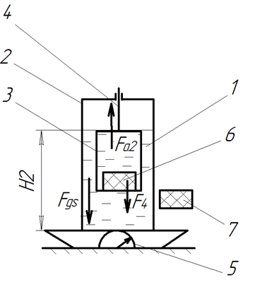
Fig. 5 An additional magnet for successful interaction and submersion of a float
If magnet 7 is attached to the wall of capsule 2, scales 5 will show the initial mass (as in Fig. 3), since magnet 7 will have already formed a single body with the capsule.
Previously one experiment was carried out (Fig. 6): completely identical liquid capsules 2, 8 with the same volumes of liquid (fresh water) 1, 9 were fixed using thread 12 on wheel 13 in the form of a pulley; moreover, each float 3, 11 was placed in each liquid capsule 2, 8, and each permanent magnet 6, 10 lay inside each float 3, 11 (the magnets were also the same in weight and magnetic force); moreover, magnets 6, 10 were located at a considerable distance so as not to interact with each other; when magnet 7 was brought closer to liquid capsule 2 at a level lower than the level of the magnet 6, the magnets 6 and 7 began to interact with each other, namely, magnet 6 turned with the opposite pole and began to attract, as a result of which it moved down, thereby dragging float 3 downwards; the total weight of liquid capsule 2 increased, and liquid capsule 2 itself began to move down, wheel (pulley) 13 rotated clockwise (Fig. 6), liquid capsule 8 went up; with the further movement of magnet 7 even lower (with the continued interaction of magnets 6, 7 with each other), liquid capsule 2 continued to move down, and liquid capsule 8 moved up.
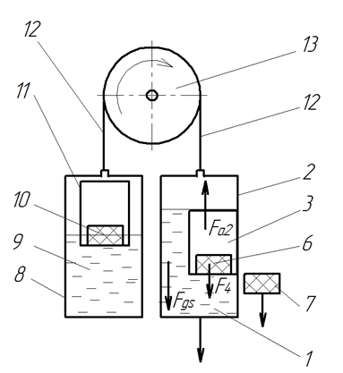
Fig. 6 An example of moving capsules due to magnets interaction
In 2021 another experimental research was conducted (see Fig. 7). In this case, capsule 2 was as a plastic cup containing liquid volume 1 and float 3 in which there was permanent magnet 6. The cup was rigidly placed on attachment 36 that was set on a special guiding part moving onto a rail. Rails 39, 43 were situated on the same level and reliably attached to wood planks 38, 46 respectively. Each rail had a moving guiding part. During cycles of experimental research planks 38, 46 were set immovable. At the top side of planks a shaft was installed in special orifices. Cord 12 was tied to guiding part 37, thrown over pulley 40. Pulley 40 was set on shaft 41, which let the pulley rotate freely. The second cord (cord 45) was connected to another permanent magnet (magnet 7), which was installed rigidly opposite to the plastic cup on the second guiding part (guiding part 47) with possibility to move onto rail 43. The cords after the pulley were tied to another dangling cord. And counterweight 44 in the form of a small metal weight was attached to cord 42. When the two magnets directed towards each other approached, they began to interact, but the counterweight did not rise. However, when the distance between the guiding parts was reduced and when the float was immersed in water, it was possible to catch a moment when the negligible distance remained between the magnets, but the second magnet was not attached to the capsule body, thereby creating a second circuit.
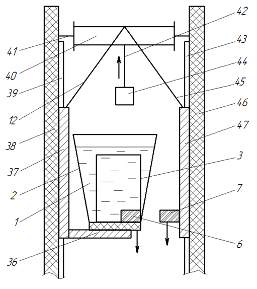
Fig. 7 Schematic view of the experimental setup to prove an effect of motion of both circuits based on interaction of permanent magnets
A movement was recorded: capsule 2 with float 3 containing the first magnet inside, together with the second magnet and both guiding parts 37, 47 moved down several centimeters, while counterweight 44 went up. Thus, it can be finally established that there is a perpetual magnetic-hydraulic engine (PMHE) of the first kind.
The successful results of the experiments served as the basis for creation of a new engine, the general view of which is shown in Fig. 8: in this case, the PMHE consists of two main circuits; the first circuit includes wheels 13, 20, that are like pulleys, liquid capsules 2 and others with the same volumes of liquid (water) in each, located at the same distance from each other and connected to each other by bracing 14 (for example, a rope, a chain, etc.) so that when rotating wheels 13, 20, all liquid capsules are driven, and in each liquid capsule there is a float with a corresponding magnet fixed in this (not shown in Fig. 8) similar to Fig. 6; the second circuit includes magnets 7, 16, located on bracing 17 at the same distance, wheels 15, 18, which are also pulleys.
The magnets of the second circuit move due to the transmission of motion from the first circuit: for example, due to reverse mechanical transmission 19 in the form of a reverse belt transmission through the input 24 and output 23 pulleys (Fig. 8). Shafts (not mentioned in Fig. 8) of wheels 13, 15, 18, 20 are fixed to the corresponding supports 21, 22, 25 and 26 which are fully stationary. Bracings 14, 17 are included in the corresponding engagement (in Fig. not marked) with wheels 13, 20 and 15, 18.
Installation of the PMHE (briefly): it is necessary to fix the wheel shafts rigidly (here not shown in Fig.) so that the wheels do not come in motion; then install the first and second circuits of the PMHE side by side at the minimum distance as in Fig. 8, i.e., so that the magnetic forces of the magnets of the first and second circuits appear, and the corresponding floats of the first circuit are immersed in the liquid to a certain level, thereby creating additional forces acting downwards.
Operation of the PMHE: if the two engine circuits are correctly installed, the wheels of both circuits will immediately start rotating after removing the brake mechanisms from the shafts (not shown in Fig.). The liquid capsules of the first circuit will start moving down on one side and up on the other side, the wheels of the first circuit will rotate clockwise, while the wheels of the second circuit will rotate counterclockwise (Fig. 8).
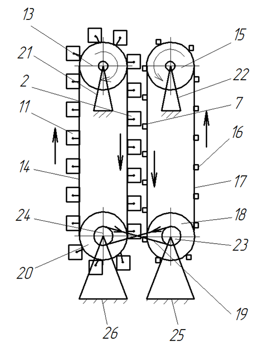
Fig. 8 Schematic view of the perpetual two-circuit magnetic-hydraulic engine with the reverse mechanical transmission
Thus, magnetic forces do not participate in the overall balance of forces, since they are horizontal. Floats on the right side of the first circuit in Fig. 8 are pressed against the corresponding walls of liquid capsules, the Archimedean forces act upwards, according to Newton’s third law other forces arise that are equal and opposite to the Archimedean forces and create additional weight. In this regard, it can be stated the following: “The gravitational force of a volume of liquid in a capsule will increase by as much as the Archimedes’ force
of the body being immersed in this liquid increases, provided that there are no direct force contacts between the capsule body containing the liquid and the body of the source of external force acting on the body.”
Advantages of the PMHE design shown in Fig. 8 are: 1) silent operation; 2) generation of free mechanical energy that can be successfully converted into electrical energy; 3) placement on a site with a small surface area (which can be effectively used, for example, in multistorey building apartment houses); 4) liquid capsules can be absolutely closed, i.e., water evaporation and constant monitoring of a liquid level are excluded. What about some disadvantages they may be the following: 1) difficulty of placing of the second circuit magnets so that they do not come into contact with the capsules of the first circuit and a constant minimum gap would be created; 2) additional installation of special guiding rails to prevent bending of the bracing (e.g., a chain, a tape, a cable, etc.) due to the action of magnetic forces, which will inevitably complicate the whole design of the engine and its weight. To avoid some disadvantages, it may be other construction with capsules and magnets similar the shown design in Fig. 7 (in this case only two shafts and two wheels are required for successful movement of both circuits).
However, another variant of the PMHE is feasible too. Consider Fig. 9, where there is no second circuit, and its magnets form a stationary magnetic line. On the one hand, the magnets of the first circuit interact with magnetic line 27 in such a way that the corresponding floats are submerged into the liquid by creating an additional force and forcing the wheels of the first circuit to rotate. At the same time, there are wheels 28, 30 to ensure the smooth movement of liquid capsules of the first circuit along them.
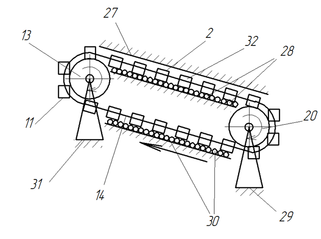
Fig. 9 Schematic view of the perpetual one-circuit magnetic-hydraulic engine with the stationary magnet line
Figure 10 shows a fragment of Fig. 9: here, magnetic line 27 interacts with magnets 6 and 33 in such a way that they push away from this (for example, magnets 6, 33 and magnetic line 27 can be directed with the same poles to each other), causing floats 3, 34 to sink into liquid volume 1, 35 (for example, water) of liquid capsules 2, 32, creating additional forces and forcing all the liquid capsules to move by means of bracing 14, rotating wheels 13, 20, thereby producing free useful work.
All floats can be made of the same material, air or other gases can be inside them. The magnets of each float must be fixed to the wall inside, although it is possible to attach the magnets to the outside of the floats, if the liquid does not lead to deterioration of properties of the magnets. Fresh or sea water can be used as a liquid.
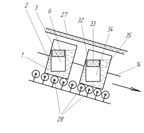
Fig. 10 Fragment of the perpetual one-circuit magnetic-hydraulic engine with the stationary magnet line
Floats should not be fixed inside liquid capsules, but should be able to move freely down and up and, possibly, in other directions. Additionally, gearboxes and electric generators can be connected to one or more wheel shafts (in the description and in Fig. not shown).
Thus, the created PMHE can be widely used for production of free work and generation of free electric energy in workshops, factories, industry, power stations and everyday life.
CONCLUSION
From all the above-mentioned there is an unambiguous conclusion: the developed PMHE can let to get free work and energy, working only on three main forces such as gravitational, Archimedes and magnetic forces. The PMHE is by far the cheapest engine in comparison with power plants on hydrocarbons or nuclear power plants. Fresh or salt water can be used as a working fluid.
It is quite possible that the developed engine will be able to work efficiently and produce electric energy in the XXI century, and therefore the environmental situation around the world will significantly improve.
The ways of further theoretical and experimental research have been outlined.
References
- Всё об экологии, проблемы, статистика, значение для человека [Электронный ресурс]. Режим доступа: https://natural-world.ru/problemy/ekologicheskaya-statistika-rossii.html - свободный. – (дата обращения 25.08.2021).
- Захаров А.Н. Глобальная энергетическая проблема: новые вызовы и угрозы, возможности их преодоления // Вестник МГИМО-Университета. 2017. 1(52). – С.187-200.
- Магнитно-гидравлический вечный двигатель:заявка на изобретение Рос. Фед. №2020102181 / Алтунин К.В.; заявл. 20.01.2020. Опубл. 20.07.2021. Бюл. №20.
- Закон Архимеда [Электронный ресурс]. – Режим доступа: https://ru.wikipedia.org/wiki/Закон_Архимеда, свободный. – (дата обращения 25.08.2021).
- Алтунин К.В. Разработка гидростатического двигателя повышенной эффективности // Международный научный журнал «Инновационная наука». – Уфа: Научно-издательский центр «Аэтерна», №3/2021. – С. 25-30.
Все статьи автора «Алтунин Константин Витальевич»
© Если вы обнаружили нарушение авторских или смежных прав, пожалуйста, незамедлительно сообщите нам об этом по электронной почте.