MODEL ANALYSIS AND CONTROL OF A SYNCHRONOUS GENERATORS
Andijan Machine Building Institute
Abstract
In this article synchronous generators have still been the most common machines used in generation since a few years before. For accurate analysis of a synchronous generator, its parameters should be identified as work as possible.
Keywords: electromagnetic fields, Park's transformation, simplified equivalent circuit of the stator, stator, synchronous generator
Рубрика: 05.00.00 ТЕХНИЧЕСКИЕ НАУКИ
Библиографическая ссылка на статью:
Арзикулов Х.М.У. Model analysis and control of a synchronous generators // Современные научные исследования и инновации. 2021. № 3 [Электронный ресурс]. URL: https://web.snauka.ru/issues/2021/03/94883 (дата обращения: 12.07.2026).
I. Introduction
We know, nowadays, nuclear power plants are important energy providers worldwide. They produce energy mainly in the form of electrical energy, the transportation and distribution of which is performed by using large-scale electrical power grid. This grid should be operated in a balanced way taking the time varying power demand of the consumers into account. From the viewpoint of the power grid the electric power generation of nuclear power is characterized by the operation of the electrical generators Besides the active power produced by a power plant, other characteristics are also of great importance. Most notably the reactive power and the frequency of the produced energy are also essential. The importance of the reactive power is indicated by the fact that insufficient reactive power of the system may result in voltage collapse. Therefore, it is widely accepted that the consumers of the reactive power should pay for it and the producers of the reactive power are enumerated. Therefore, the power controllers of nuclear power plants should also take the production of the reactive power into account. [1]
II. Main part
Thereafter, the two stator electromagnetic fields, both traveling at rotor speed, were identified by decomposing each stator phase current under steady state into two components, one in phase with the electromagnetic field and the other phase shifted by 90o. With the aboves, one can construct an airgap field with its maximum aligned to the rotor poles (d axis), while the other is aligned to the q axis (between poles) [2]
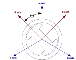
Picture 1. The abc and 0dq frames of the generator.
The 0dq coordinate of frame is fixed to the rotor, abc coordinate frame is fixed the stator flux
This change in the coordinates is called the Park’s transformation that gives
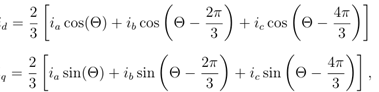
where ia, ib and ic are the phase currents and Θ is the angle between the phase current ia and the current id.
The Park’s transformation uses three variables as d and q axis components (id and Iq) and the last one is the stationary current component (io), which is proportional to the zero-sequence current. By denoting vectors by boldface and matrices with capital boldface letters can write the new current components from the relationship
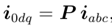
where the current vectors are

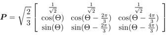
And the Park’s transformation matrix is
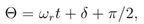
All flux components correspond to an electromagnetic field (EMF), the generator EMF is primarily along the rotor q axis. The angle between this EMF and the output voltage is the machine torque angle δ, where the phase a is the reference voltage of the output voltage. The angular position of the d axis (in radian) is in the form [3]
The equivalent circuit of the synchronous machine is depicted in picture-2
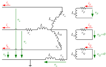
Picture-2. The simplified equivalent circuit of the stator and rotor circuits of synchronous machine
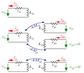
Picture-3. The simplified equivalent circuit of the transformed stator and rotor circuits
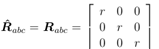
As it was assumed, the machine has symmetrical tri-phase stator windings (ra = Rb = rc = r), so the resistance matrix Rabc is in the following diagonal form [4]
The second step is to compute the time derivatives of the fluxes as
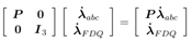
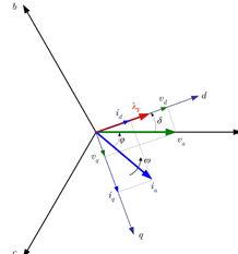
Diagramma-1.The voltages, currents and the flux of the synchronous machine in abc and dq coordinate system, where ϕ is the phase offset, δ is the load angle and ω represents the angular velocity of the EMFn [5].
III. conclusion
As a result of the sensitivity analysis, it is possible to define the following groups of parameters: Not sensitive inductances ld, lq, lD, lQ, LMD, LMQ, LAQ, LQ, damping constant D and the controller parameters P and I. Since the state space model of interest is insensitive for them, the values of these parameters cannot be determined from measurement data using any parameter estimation method.
References
- J. Alvarez-Ramirez, H. Puebla, and G. Espinosa. A cascade control strategy for a space nuclear reactor system. Annals of Nuclear Energy, 28:93–112, 2001.
- H. Amaris and M. Alonso. Coordinated reactive power management in power networks with wind turbines and facts devices. Energy Conversion and Management, 52(7):2575–2586, 2011.
- P. M. Anderson, B. L. Agrawal, and J. E. Van Ness. Subsynchronous Resonance in Power Systems. IEEE Press, New York, 1990.
- P. M. Anderson and A. A. Fouad. Power Systems Control and Stability. The IOWA State University Press, Ames Iowa, 1977.
- Attila Fodor. Model analysis, Parameter Estimationand Control of a Synchronous Generator PhD thesis. DOI: 10.18136/PE.2015.583
Все статьи автора «Режабов Зайлобиддин Маматович»
© Если вы обнаружили нарушение авторских или смежных прав, пожалуйста, незамедлительно сообщите нам об этом по электронной почте.