1Андижанский машиностроительный институт, Узбекистан
METHODS OF GRAPHIC AND MATHEMATICAL DESIGN OF ENGINEERING OBJECTS
1Andijon machine-building institute, Uzbekistan
Abstract
Today, all areas are developing in close connection with information technology. In the field of CAD, software packages with different approaches have been developed and are now in a professional state. While AutoCAD, 3Ds Max, and many other programs design objects graphically, MathCad can create object designs using mathematical functions.
In graphic form, the possibility of designing more complex objects will be wide. Mathematical design, on the other hand, is characterized by a high degree of precision.
Keywords: automated design systems, CAD, CAE, CAM, information technology
Рубрика: 05.00.00 ТЕХНИЧЕСКИЕ НАУКИ
Библиографическая ссылка на статью:
Mullajonov B.A., Mamirov H.H. Methods of graphic and mathematical design of engineering objects // Современные научные исследования и инновации. 2020. № 6 [Электронный ресурс]. URL: https://web.snauka.ru/issues/2020/06/92641 (дата обращения: 31.07.2026).
The role of information technology is very high in an era of rapid development of technology and innovative technologies. Nowadays, information technology has penetrated into all spheres and has become an integral part of it. Modern information technologies are entering the field of education, creating opportunities for teaching methods and the organization of the educational process with modern approaches. Therefore, the quality of the educational process is increasing. Information technology is a method of processing information with various software and hardware . When it comes to information technology, it is impossible not to talk about the concept of computers. The most powerful and multifunctional device ever created by scientists is the computer. Today, computers have entered every field, it is impossible to bypass it.
It affects our activities in some way anyway. The number of computer services is growing and the work we do is becoming easier.[1]
The use of information technology tools is very effective in creating convenient models that fully meet modern requirements in the production process . CAD, CAM, CAE programs are widely used in automated design systems in the description of certain details of cars, in the creation of modern models and in the design process. During production, engineers go through three stages. In the CAD system, the design and automation of drawings are considered. In the CAM system, the process of making a mold of parts is carried out. The CAE system calculates the parameters of the structure, such as load-bearing capacity, strength, durability. These processes are an important factor in product creation. Below we will talk in detail about CAD, CAM, CAE systems.
CAD Systems (Computer aided design – Design of drawings on the computer) are designed to create a computer project of drawing ideas and documents of constructiveness. Currently, the module of CAD systems includes the creation of three- dimensional structures and the design of drawing design documents. Examples of such documents are manuscripts, specifications and other similar documents. CAD System Packages Let’s look at the generalities and specifics of AutoCAD and MathCAD:
-In AutoCAD, the drawing project is illustrated graphically, in which mathematical formulas are almost not used. This program allows a person to create complex objects in a graphical way, as the interface, which at first glance looks very complex, actually has many features.
In MathCAD, the drawing project is based on mathematical formulas. With a deep understanding of mathematical functions, we will be able to create even the most complex objects with high accuracy.
CAM systems (Computer aided Manufacturing) are designed to be designed on digital software control machines during product development.. CAM systems are focused on creating software for machines. That is milling, drilling, and the like. In practice today, they are the only system for reducing the time in the creation process and creating complex profile details. Also, CAM systems are also called systems for preparation for technological production activities. CAM systems, like CAD systems, use three-dimensional models of the product created in the project.
CAE systems (Computer aided engineering-design of complex calculations) are a comprehensive system. In this system, precise engineering computations are performed. Examples of such works are: analysis and modeling of thermal phenomena , design of hydraulic systems, machine calculations, design of casting processes, calculation of units and strengths. CAE systems are these engineering analysis systems. This system uses three-dimensional models of the product designed on the basis of CAD systems.
The process of creating a project based on human-computer communication is called automated design systems. This process is an automated process. Abroad, CAD, and in the Commonwealth of Independent States, systems called ADS (Automated Design Systems) are automated design systems. But keep in mind that the concept of CAD or ADS(Automated design sytems) has many meanings. That is why it is a big mistake to understand only the drawing project when we say CAD or ADS. Depending on the scope of application of these concepts, the essence of its content may change.
The first automated design system appeared in the 60s of the twentieth century . At the Massachusetts Institute of Technology in 1955-1959, under the leadership of Ross, the software system API (Automatical program tool) was created. For the first time, Ivan Serenland introduces the concept of CAD to science. Ivan Selender’s doctoral dissertation in this field is based on machine graphics. Later, scientists from around the world and Uzbekistan worked hard in this area . Of particular note are the works of world scientists Kunwoo Lee, VN Malyukh , ALBochkov, IP Norenkor, and the works of our scientists B. Tola. B. Tulayev’s book “Automation of planning processes ” , published in 2008, contains a lot of useful information in this area. A person entering this field is required to have a thorough knowledge of the field related programs. Examples of the most modern such programs are: AutoCAd, UGS NX, 3Ds Max, MathCAD and others . Below we will focus on each program separately.[2]
AutoCAD was developed by the American company Autodesk in the 80s of the twentieth century. Not long after this program was developed, it became widely popular as a program for editing drawings on a computer. The main factors that have made AutoCAD so popular around the world are:
- Elimination of shortcomings, taking into account the advice and objections of users ;
- Constantly changing the program;
- Integration with Microsoft operating system;
-Development in a way that is compatible with other system software and application software packages;
AutoCAD is the perfect program to work with three-dimensional projects, as it originally worked with two-dimensional drawing projects.
UGS NX was created in 1978 by Siemens PLM Software. This program works on files in SIL format. Works on Unix, Linux, Mac OS X, Microsoft Windows operating systems. In addition to performing design work in the CAD system, the UGS NX program can also perform engineering analysis in the CAE system. The creation of UGS NX and similar software has opened the door to enormous opportunities in the field of CAE systems. Testing of collision processes using a three-dimensional model of the car, designed in the UGS NX program, determines the stiffness and strength of the car in various situations of collisions . In the absence of such CAE programs, the manufacturing company would test these models through real-world collisions. This, of course, leads to an increase in economic costs. The UGS NX software includes many modules, and these modules vary from one to another depending on the area in which they are used. The interface can seem very complicated when the user initially uses this program. The only reason for the complexity of the interface is that UGS NX software has a very wide range of capabilities.
The 3Ds Max software was developed by Autodesk in 1990. This program is one of the most modern and convenient programs for three-dimensional modeling and the creation of anemations of this set of models. This app has a separate section that works with lighting, which makes it superior to other apps. The program is equipped with the most advanced toolbar for multimedia professionals. It is capable of running on all modern versions of the Windows operating system. 3Ds Max software gives the user a wide range of freedoms. If the user wants, the screen can be divided into four, and the object can be viewed from four sides. Alternatively, the user can still work in normal single window mode.[3]
MathCAD differs from the above-mentioned programs by its simplicity of interface. As you learn MathCAD, you will become convinced that there are many aspects that you may not have noticed at first. The simplicity of the interface at first glance does not preclude the fact that the program has many extensive features. If the expression entered in MathCAD turns red, it means that there is an error. In this case, the error should not be seen from the program running. The error should be searched for in the entered part of the expression. This is because MathCAD has the ability to solve many expressions that are entered correctly. With the help of this program we can clearly solve the following expressions.
- Solving linear and complex algebraic equations and systems of equations;
- Solve simple differential equations and systems of equations;
- Working with vectors and matrices;
- Maximum and minimum search for functional dependence;
- Solve differential equations with special derivatives;
- Creating graphs of single and internal argument functions;
MathCAD software is enriched with formulas for mathematics, physics and chemistry, toolbars with programming elements. One of the important aspects of MathCAD is that it is possible to create a graphical representation of any object through a system of mathematical functions and expressions.[4]
Below we will look at creating three-dimensional graphs and objects based on mathematical formulas in 2 different ways . We use 3Ds Max to create objects graphically. We use MathCad to create an object using mathematical formulas .
n:=120
i:=1…n j:=1…n

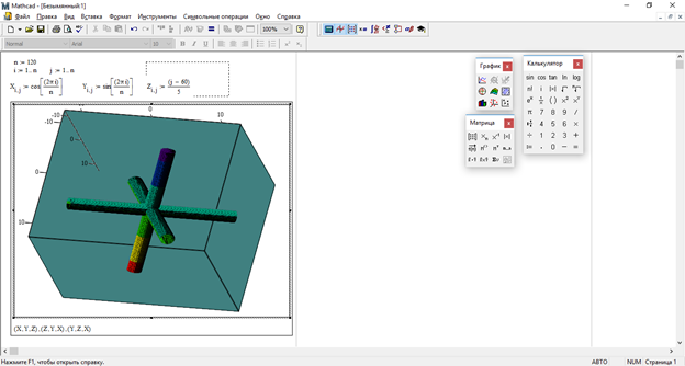
Figure 1. Mathematical construction of three cylinder intersections in MathCad
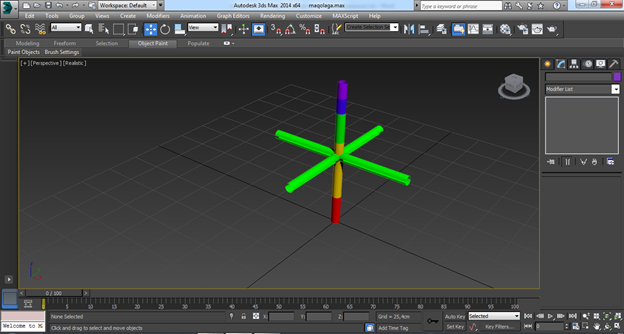
Figure 2. Creating a three-cylinder intersection graphically in 3Ds Max
ORIGN :=0
N :=60 i :=0…N j :=0…N

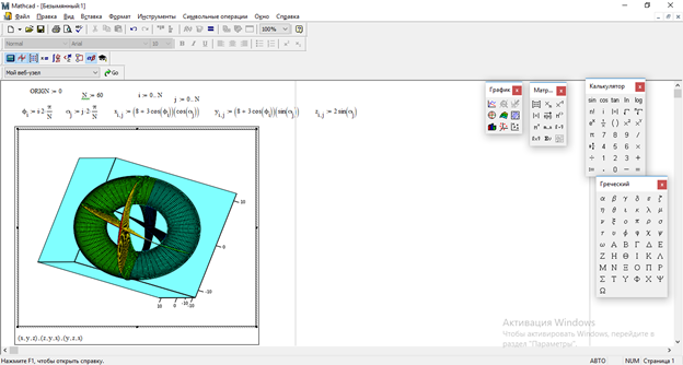
Figure 3. Creating a three-dimensional logo from a combination of three shapes in MathCad
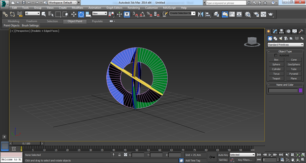
Figure 4. Create logo in 3Ds Max
ORIGN :=0
N :=60 i := 0…N j :=0…N

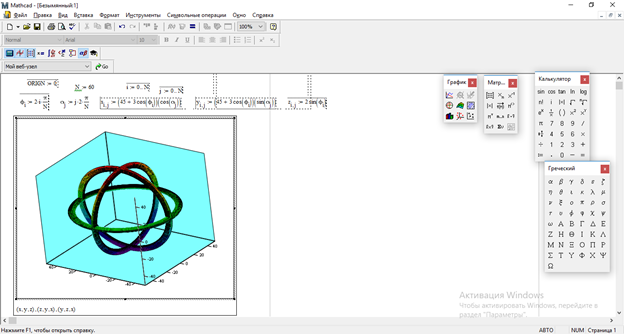
Figure 5. Intersection of three circles in MathCad
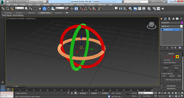
Figure 6. Intersection of three circles in 3Ds Max
The widespread use of the above-mentioned modern software in enterprises leads to the development of automated design systems. The teaching of these programs in educational institutions that provide education in the field will be the basis for the training of modern personnel.
|
№ |
Differentiation |
1-method graphics In the 3 Ds Max program |
Mathematical method 2 In the Matcad program |
|
1 |
Time spent |
Medium |
Fast |
|
2 |
Degree of accuracy |
Good |
It has a high degree of accuracy |
|
3 |
Ability to edit created objects in other programs |
Ability to process in AutoCAD and NX programs |
It is not possible to process objects in other programs |
|
4 |
Ability to colorize objects |
The color palette is rich in color and the ability to choose the type of material for objects |
The color palette is not as rich as the 3 Ds Max software palette |
It can be concluded from the table that objects created by a mathematical formula have a high degree of accuracy and are also more productive by the time spent. Objects created in a graphical way are distinguished by the possibility of easy use in other related programs and the richness of the color palette, the ability to provide material to the object. For the development of automated design systems in enterprises, it is necessary to be able to use both of the above methods where necessary. Teaching the necessary programs working in these ways in the relevant educational institutions will be the basis for the development of modern personnel.
References
- Tulaev B. Automation of design processes.-T .: TSTU, 2008.
- Makarov E. Engineering calculations in Matt S ad . Izd .. Peter. M. 2003g.
- Kunwoo Lee. Principles_of_CAD_CAM_CAE_systems. Addison-Wesley 2013.
- Dugan Um. Soild Modeling and Applications. CAD / CAE. Rapid Prototyping / Springger. United States of America, 2016.
Все статьи автора «Режабов Зайлобиддин Маматович»
© Если вы обнаружили нарушение авторских или смежных прав, пожалуйста, незамедлительно сообщите нам об этом по электронной почте.