An important stage in the development of modern mechanical engineering and in particular construction and road machinery, is the use of methods of unification and standardization of the main basic components and parts, which reduces labor costs for development, design and manufacture and, as a result, improve the quality, reduce the energy intensity and cost of the developed machines.
At the same time, the unification of vibration machines for compacting concrete mixtures is understood as a rational reduction of the variety of types of vibration exciters, elastic shock absorbers, connecting nodes, structures of movable and support frames that have the same functional purposes.
At the same time, the creation of a wide range of modifications of the main basic machines for a certain type of technological process with a high coefficient of unification ![]() =75…80 % will allow you to get higher indicators in the complex mechanization of construction, improve the quality of manufactured products and increase their maintainability.
=75…80 % will allow you to get higher indicators in the complex mechanization of construction, improve the quality of manufactured products and increase their maintainability.
Vibration exciters are the main components of vibration platforms for forming cement-concrete mixtures. Their design has a significant impact on the performance, overall line-up and design, as well as on the energy and metal consumption of vibration platforms. Vibration exciters should be easily integrated into the structure of the vibration platform, be compact, have a small metal capacity, have a relatively simple design and ease of maintenance during operation, as well as generate a sufficiently powerful disturbing effect in a certain direction according to a certain law. Based on these requirements, we have developed vibration exciters with unbalanced shafts, rotary vibration exciters and planetary vibration exciters designed for use on horizontal and spatial vibration platforms with one – and two-frequency vibration effects on the compacted cement-concrete mixture.
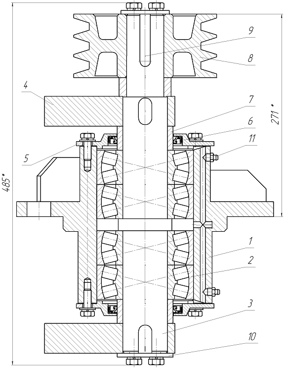
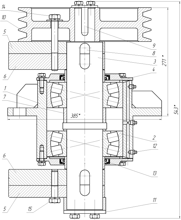
To drive vibration platforms with horizontal and spatial vibrations of the movable frame, vibration exciters were developed (Fig. 1, 2) with high and low vibration frequencies, which are installed on vibration platforms with a load capacity of 5 – 40 tons, designed for forming concrete products of various configurations from plastic and rigid concrete mixtures.
The high-frequency vibration exciter (Fig. 1) includes a housing 1, which is made in the form of a cylinder with a flange support. Inside the housing are four radial double row spherical roller bearing 2, within which is mounted a drive shaft 3. The shaft 3 has 2 imbalance 4. Each of the imbalances is installed outside the housing 1. The ends of the cylindrical casing 1 closed by end caps 5 which includes the seal 6. To separate the pairwise mounted roller bearings 2 and form a cavity in the central part of the housing for lubrication, a collar is provided on the shaft 3. Spacer bushings 7 are installed between the bearings 2 and the unbalances 4. The unbalance shaft is driven through the V-belt transmission pulley 8. With the help of key connections 9, unbalances 4 and a pulley 8 are mounted on the bearing shaft, to prevent displacements of which in the axial direction, end washers 10 are provided. On the housing 1, oilers 11 are installed, which serve for periodic supply of lubricant to rolling bearings through special holes made in the housing. Thanks to the specially designed grooves in the pass-through covers 5, grease freely enters the upper and lower bearings.
On a high-frequency vibration exciter, unregulated imbalances are usually used.
The low-frequency vibration exciter (Fig. 2) differs from the high-frequency vibration exciter in its design. It uses only 2 radial spherical double row roller bearings and uses adjustable unbalances that allow you to change the amplitude of the disturbing force.
Adjustment of the amplitude of the disturbing force is carried out as follows. At the beginning, the bolts 14 and 15 are unscrewed. Then the debalances 5 are deployed relative to the debalances 6 and fixed in one of the four positions. To do this, the debalances 5 are freely planted on the shaft 3 and four holes are made in them, and the debalances 6 are connected to the shaft 3 by a key connection.

Figure 1 – High-frequency vibration exciter

Figure 2 – Low-frequency vibration exciter: 1 – housing; 2 – bearing; 3-shaft; 4 – Bearing cover through passage; 5-movable debalance; 6-fixed debalance; 7-spacer sleeve; 8-special key connection; 9-key connection; 10-pulley; 11-end washer; 12-oiler; 13-cuff; 14, 15-adjustment bolts
To ensure the most favorable operation of the bearings under circulating load, the following landings were selected: on the shaft according to ![]() , in the housing according to
, in the housing according to ![]() .
.
Litol M was used to lubricate the bearings.
In the process of calculating rolling bearings, a method was used that is based on information on the recommended resources of bearing units for machines and equipment for various purposes in accordance with current standards and updated characteristics of the most common standard bearings.
The dynamic load capacity of the bearing is determined by the known dependence:
![]() , (1)
, (1)
where ![]() – is the equivalent dynamic load;
– is the equivalent dynamic load;
![]() – bearing life in millions of revolutions;
– bearing life in millions of revolutions;
![]() – exponent, for roller bearings
– exponent, for roller bearings ![]() =10/3.
=10/3.
When calculating vibration exciters, a 90% probability of trouble-free operation of bearings, which is typical for general-purpose machine supports, and their heavy operating mode were assumed. Then, for radial spherical double row roller bearings used in vibration exciters with low and high vibration frequencies, the equivalent dynamic load can be determined from the following dependence:
![]() , (2)
, (2)
where ![]() – amplitude of the disturbing force of the vibration exciter;
– amplitude of the disturbing force of the vibration exciter;
z – number of load-bearing bearings in the vibration exciter;
![]() – operating mode coefficient, for heavy duty operation
– operating mode coefficient, for heavy duty operation ![]() =0,8;
=0,8;
![]() – the safety factor,
– the safety factor, ![]() =1,3;
=1,3;
![]() – coefficient that takes into account the rotation of the outer ring of the bearing.
– coefficient that takes into account the rotation of the outer ring of the bearing.
Estimated bearing life in millions of revolutions
![]() , (3)
, (3)
where ![]() – angular frequency of forced oscillations, rad / s;
– angular frequency of forced oscillations, rad / s;
![]() – estimated service life of the bearing in hours.
– estimated service life of the bearing in hours.
Substituting expressions (2) and (3) into formula (1), we determine the amplitude of the disturbing force of the vibration exciter depending on the size of the selected bearings and their number in the vibration exciter
.gif) , (4)
, (4)
where ![]() – dynamic load capacity of a certain bearing size.
– dynamic load capacity of a certain bearing size.
Table 1 shows the values of the dynamic load capacity of radial spherical double-row roller bearings 3612 and 3618 with a brass cage, having an accuracy class of 0, which were used respectively in the creation of vibration exciters with high and low vibration frequencies.
Technical characteristics of high-frequency vibration exciters (Fig. 1) are given in Table 2, and low-frequency vibration exciters (Fig. 2) are given in Table 3. For a comparative assessment of vibration exciters, the ratio was used ![]() , that is, the ratio of the amplitude of the disturbing force to the mass of the vibration exciter.
, that is, the ratio of the amplitude of the disturbing force to the mass of the vibration exciter.
Table 1 – Characteristics of deep groove roller bearings and ball bearings used in the proposed vibration exciters.
|
Designation of the bearings
|
Dimensions, mm
|
Load capacity,kN |
Speed of rotation,Rpm, when greasing * |
|
|
|
|
|
|
3612
|
60
|
130
|
46239,1261,128003600
|
|
3618
|
90
|
190
|
64445,3550,818002400
|
|
320
|
100
|
215
|
47217,3207,827003500
|
| * k - grease; g - liquid lubricant | |||
Table 2 – Technical characteristics of high-frequency circular vibration exciters.
|
No.
in order |
Name of
indicators |
Type of vibration exciter
|
| В1-335В1-292-1В1-292-2В1-292-3В1-272-4 | ||
|
1
|
Angular frequency of forced oscillations, rad / s |
335292292292272
|
|
2
|
Static moment mass debalance, |
71,2597,25117,54140,4190
|
|
3
|
Amplitude of the disturbing force, kN |
8082,9100,2119,7140,5
|
|
4
|
Mass of the vibration exciter, kg |
83,685,788,289,297,5
|
|
5
|
0,9570,9631,1361,3421,44
|
Table 3 – Technical characteristics of low-frequency circular vibration exciters.
|
No.in order |
Name of
indicators |
Type of vibration exciter
|
|
В2-175В2-190В2-204
|
||
|
1
|
Angular frequency of forced oscillations, rad / s |
175,2189,6204,4
|
|
2
|
Static moment mass debalance, |
463,5; 401,4327,7; 231,8385,7; 334,0 272,7; 192,9320,9; 277,9 226,9; 160,5 |
|
3
|
Amplitude of the disturbing force, kN |
142,3; 132,2100,6; 71,2138,9; 120,3 98,2; 69,5134,0; 116,0 94,7; 67,0 |
|
4
|
Mass of the vibration exciter, kg |
164,6155,6147
|
|
5
|
0,8640,8930,911
|
The proposed vibration exciters with shafts on which debalances are installed have a relatively simple and compact design, are easily integrated into the central part of the vibration platform and have a reliable attachment. Due to the compact design and symmetrical arrangement of unbalances relative to the flange supports, they do not create overturning moments during operation, thereby ensuring the uniformity of the vibration amplitudes of the movable frame of the vibration platform along its entire length, which positively affects the quality of the molded product. Long-term operation of vibration exciters with unbalanced shafts has shown that they are quite reliable in operation and do not require time-consuming maintenance. The proposed low-frequency and high-frequency vibration exciters can be installed together on one movable frame of the vibration platform or separately.
По соотношению ![]() предлагаемые вибровозбудители колебаний имеют наилучшие показатели по сравнению с известными, выпускаемыми промышленностью вибрационными возбудителями колебаний.
предлагаемые вибровозбудители колебаний имеют наилучшие показатели по сравнению с известными, выпускаемыми промышленностью вибрационными возбудителями колебаний.
References
- Maslov, A.G., Zhanar Batsaikhan “The Research of oscillations of the machine working body of the for compaction of concrete mixes in vibration working mode”, Transactions of Kremenchuk Mykhailo Ostrohradskyi National University. Kremenchug: KRNU, 2015, Issue (91), pp. 92 – 97.
- Maslov A., Janar Batsaikhan, Puzyr R, SalenkoYu. The Determination of the Parameters of a Vibration Machinef the Internal Compaction of Concrete Mixtures. International Journal of Engineering & Technology, 2018, Vol. 7 (4.3), pp 12-19.
- Maslov O., Janar Batsaikhan, SalenkoYu. The Theory of Concrete Mixture Vibratory Compacting. International Journal of Engineering & Technology, 2018, Vol. 7 (3.2), pp 239-244.
- Maslov A., Janar Batsaikhan. The research of the parameters of a vibration machine for composite materials compaction. MATEC Web of Conferences, 2018, 224, 02099.
- Nesterenko M., Maslov A., Salenko Ju. Investigation of Vibration Machine Interaction With Compacted Concrete Mixture. International Journal of Engineering & Technology, 2018, Vol. 7 (3.2), pp 260-264.
- Маслов А.Г., Саленко Ю.С. Вибрационные машины и процессы в дорожно-строительном производстве. – Кременчуг: ЧП Щербатых О.В. – 2014. – 262 с.
- Маслов А.Г. Иткин А.Ф., Саленко Ю.С. Вибрационные машины для приготовления и уплотнения бетонных смесей. – Кременчуг: ЧП Щербатых А.В. – 2014. – 324 с.
- Maslov, A.G., Salenko, Y.S. (2014), Vibratsionnyie mashinyi i protsessyi v dorozhno-stroitelnom proizvodstve: monographiya [Vibrating machines and processes in road construction industry: monograph], PР Cherbatyh, Kremenchuk, 2014, Ukraine.

 View this article in Russian