 View this article in Russian
Introduction
Currently engineers who design and analyze chemical engineering schemes (CES), must be able to create and share databases of developed schemes. Such schemes include their graphical representation and calculated results. However, now most of these schemes exist in some graphical format of the drawing software (AutoCad), which is not integrated, or poorly integrated (via VBA) with a performance of CES calculations. Specialized commercial systems provide such an opportunity based on proprietary formats, but most of them are not designed for computer synthesis based on the non-graphic description of the technological schemes.
Problem formulation
In our opinion, specialized public computer formats are necessary for the effective information exchange between the developers of CES (both public and commercial systems). In this way, the scheme should be objectively presented, regardless of the style and the technical taste of the developer. So, the scheme must be unified. In other words, the scheme, which was made by different people using textual description or non-unified drawing, will look the same, and computer-generated descriptions will be also identical. This identity will not only improve communication between developers but will also make it possible to maintain databases of possible CES configurations.
Analysis of research and publications
Unified ways of presenting different information (graphic, text, numerical) in XML and its derivatives (GraphML) are widely used in modern programs. However, there are no unified ways of CES representation, primarily in configuration aspect. Different experts using a textual description of process steps and their sequence, including recycles and bypasses will draw different schemes realizing the same description. Coding such schemes in the XML format will give identical files, and the more complex the scheme is, the more options of the text description are. Thus, in programs that use XML to describe the calculation schemes (for example, Xcos SciLab), CES parameters will be calculated several times with the same result. Another significant problem is a lack of a single CES representation during expert software development of technology schemes synthesis. The program cannot distinguish between different versions of the same description of the some scheme and different schemes which realize the same problem without the unified approach to the scheme description.
A common rule of advanced calculations, including calculations of chemical and engineering industries, is “withholding” of computing procedures through the provision of services by any graphical interface. Also, universal program complexes (Hysys, ChemCAD, etc.) for calculating chemical processes do not provide information about saving the structure of CES. Such closeness raises a number of organizational and technical problems.
After examining a number of publications, initiatives aimed at the unification of the exchange and presentation of CES topology were identified. In particular, it was XMLPlant [1], which used XML. An XML document consists of text characters and is suitable for reading by human and computer processing in order to storage structures. Another program is CAPEOpen [2], which is a standard of data exchange between programs of chemical technology modeling. These initiatives have not got recognition among manufacturers of software systems. There are some software products on the market that allow you to calculate the flows of CES, but all these programs strictly limit data exchange.
Unification of CES presentation
We propose a unified way of CES drawing (Figure 1). It allows creating the table (Table 1) and encoded text descriptions of engineering schemes. Then obtained codes are translated into XML format and are used directly in programs using languages of general or special purpose.
Table 1. Table CES description
|
A |
B |
C |
D |
|
|
1 |
Initial water |
1st stage of RO |
2nd stage of RO |
Desalted water |
|
2 |
Concentrate recycling on the 1st stage |
Concentrate 1 |
||
|
3 |
Concentrate recycling on the 2nd stage |
Concentrate 2 |
||
|
4 |
Waste |
Sewage waters on the 1st stage |
Sewage waters on the 2nd stage |
It was an example of a 2-stage reverse osmosis (RO) installation. It shows that there is an opportunity to perform simple text encoding of lines with equipment (capital letters) and without them (lower case letters). Recycling is described using reverse (in alphabetical order) sequence of letters:
1:aBCd;2:ba;3:ca;4:b2c3.
Upper horizontal processing line (level 1) is the main flow (from the initial substances to the key product). Choice of the main flow is based on different factors, for example, productivity, a number of devices (if the line with the maximum flow rate is not obvious), functionality (in processes of water purification). Choice of the main factor is agreed on beforehand. The sequence of the next levels depends upon the order of the following levels. Lines with equipment are usually higher than lines without it (recycling and bypass).
Proposed way of CES representing does not always use the space of the drawing sheet effectively, but it allows you to get the same drawings and code by experts who use text description or non-unified scheme. In addition, formal scheme control is improved (number of levels for the technology and text encoding). That is important in teaching and for designing critical engineering areas.
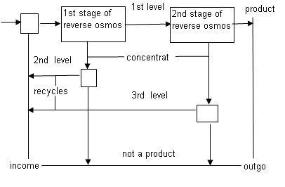
Figure 1 – Two-stage RO installation scheme with partial concentrate recycling (Excel editor).
XML based configuration of CES
There is software for a unified representation of CES. Those programs can use CES for analyzing and choosing the best configuration after performing some calculations.
It is recommended to use yEd as the best editor to realize such an idea. This editor has worked well on all popular platforms and has algorithms for automatic visualization of the arbitrary graph structure. In addition, the editor stores information in GraphML format (based on XML), and that allows performing the calculation of a scheme using information about its configuration.
For example, Figure 2 shows the scheme of RO installation, that was created in yEd.
The used tool gives the opportunity not only to set the topology of the water consumption scheme but also to set the parameters of the devices and streams that will be saved along with the configuration of the scheme (in XML file). In the illustrated example such parameters are flowrate and composition of the input streams for the 1st and the 2nd stages of water treatment.
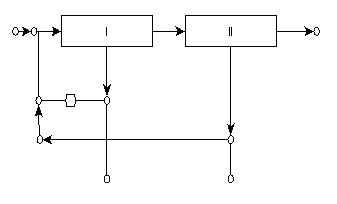
Figure 2 – Two-stage RO installation scheme with partial concentrate recycling (yEd editor).
Shortened recording of the scheme (XML-file fragment describes one of the graph edges) is as follows:
<edge id = “e0″ source = “n0″ target = “n2″>
<data key = “d10″>
<y: ArcEdge>
<y: Path sx = “0.0″ sy = “0.0″ tx = “0.0″ ty = “0.0″>
<y: Point x = “85.0″ y = “112.0″ />
</ y: Path>
<y: LineStyle color = “# 000000″ type = “line” width = “1.0″ />
<y: Arrows source = “none” target = “standard” />
<y: Arc height = “0.0″ ratio = “0.0″ type = “fixedRatio” />
</ y: ArcEdge>
</ data>
</ edge>
It could be seen that topology and visualization data are partially mixed. It is not essential in further scheme calculation using programs because the structure of XML format allows you to choose data that you need for a particular application.
XSLT technology can be used in order to create automatically a unique index which will identify the scheme. XSLT (eXtensible Stylesheet Language Transformations) – is a language of XML-documents transformation. XSLT specification is a part of XSL and is recommended by W3C.
Graph format based description
The proposed approach to coding CES has a disadvantage. It is redundant information for the specialist in the subject area. On the other hand, table-based representation does not use paper space efficiently when drawing.
Currently used text formats for coding graphs don’t have the first disadvantage. Special programs (for example, free GraphViz and yEd) have a variety of options for displaying a predetermined configuration. That optimizes the space of the sheet to display the scheme and overcomes the disadvantages of a table view.
The are two graph formats: TGF (Trivial Graph Format) and DOT (extension .gv or .dot). DOT format (GraphViz) is not suitable for yEd, but you can convert DOT into GraphML to run it in yEd.
Explicit representation of a mixer and a separator in a directed graph is used in order to represent a single-stage scheme of RO installation in DOT-format (undirected – graph):
digraph osmos1 {
“mixer” -> “membrane” -> “permeate tank”;
“membrane” -> “separator” -> “mixer”; // concentrate recycling
“Separator” -> “sewage tank”;
}
The sequence of relation descriptions in a graph is not important. For example, if you put the line with concentrate recycling at the third line and not at the second one, then the graph will be displayed by the identical manner according to the display style. However, textual representations of the two options (after converting a text file into a string) will be different when using computer functions of line comparison. Consequently, the proposed unification of CES representation (sequence of scheme levels) remains relevant for the described formats, since it provides an unambiguous identification of schemes with horizontal encoding.
Conclusions
Thus, the use of the proposed approach is useful for synthesis, calculations and analysis of any chemical and engineering schemes. The format of technological schemes based on tables, graph formats, XML (GraphML) and related information technologies will reliably verify the schemes and provide access to their extensive reciprocal exchange, including commercial basis.
Further calculations using data on the scheme configuration and its parameters can be implemented on general-purpose languages (Python, VBA), as well as in specialized mathematical programs (SciLab, MatLab).
References
- Valter James, Stahl David. Technology for Interoperability [Текст]. N.Y., Wiley, 2009. 150 с.
- CAPE-OPEN Laboratories Network (CO-LaN) [Электронный ресурс] - Режим доступа: http://colan.org.